TL;DR
- Linear perspective: a 3D point is projected by intersecting the line from the point to the viewpoint with a picture plane. By similar triangles : twice as far means half as big. The division by makes the projection non-linear.
- A bare sensor gives a blurred image. A pinhole gives a sharp linear perspective but is too dark. A lens gathers more light and still gives a linear perspective, but only one plane is in focus. Gaussian lens formula: .
- Forward projection goes through four coordinate systems: world → camera → film → pixel. Only camera → film loses information (depth).
- Homogeneous coordinates turn the projection into a matrix product. The whole chain is one matrix .
- Extrinsics (where the camera is) with . Intrinsics (how the camera is built).
- Orthographic projection drops . It is a good model for telephoto and telecentric lenses.
The lecture has two parts: an introduction to image formation, then the mathematical formalization with the projection matrix.
Part 1: Image Formation, Introduction
Why Image Formation?
Slides 3-5
Computer vision goal: predict the 3D world from a single image. For example, recover the 3D mesh of a human (pose and shape) from a photo. This means we have to invert the image formation process.
Computer graphics goal: the reverse problem. Given controls for shape, pose and clothing, generate realistic images of humans.
The boundaries between the two fields are more and more blurred: we often need to solve both problems at the same time. For both, we first need to understand image formation: the physical process that captures the light emitted by a 3D scene and produces an image.
The Laws of Perspective
Slides 6-11
Common assumptions:
- Light leaving an object travels in straight lines.
- These lines converge to a point at the eye.
Natural perspective (Euclid, 3rd c. B.C.)
More distant objects subtend smaller visual angles. If an object comes closer to the eye, the angle becomes larger than .
Roman wall paintings (Pompeii, Herculaneum) follow natural perspective: distant objects are smaller, but the proportions are not quite right and the paintings look flat. Natural perspective is not enough, they need linear perspective.
Linear perspective (Filippo Brunelleschi, 1413)
A perspective image is formed by the intersection of the lines of sight with a picture plane (the canvas).
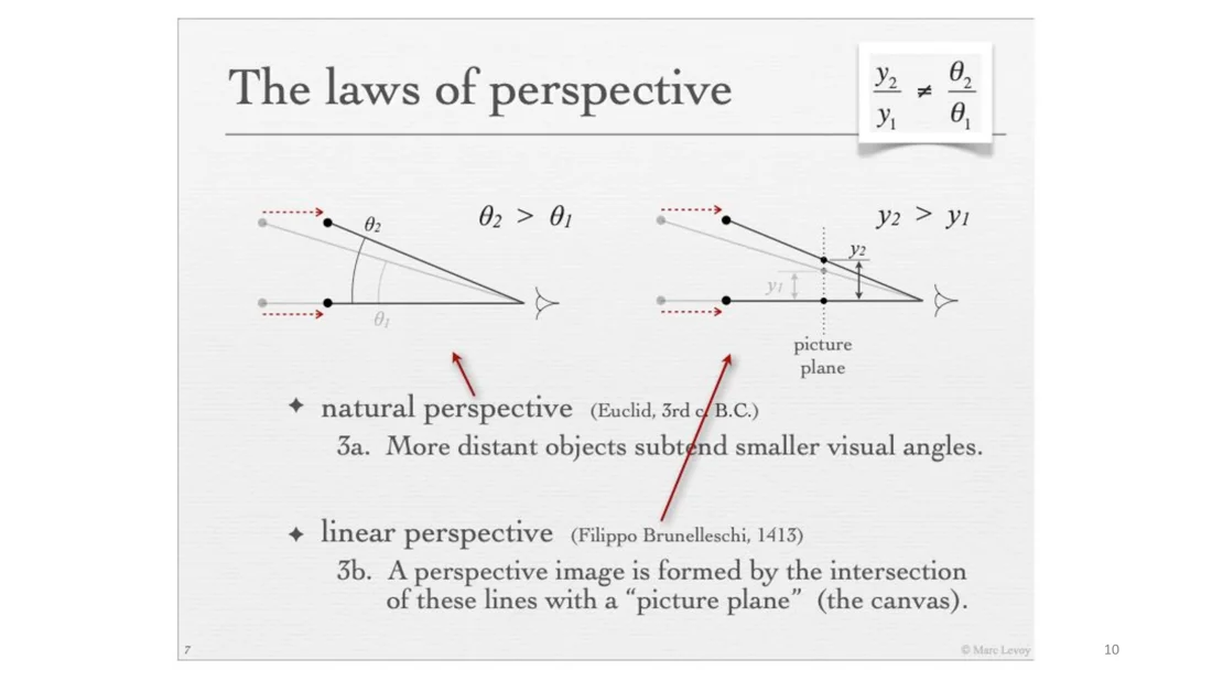
In linear perspective, the two black dots of the object are projected by intersecting the straight line from each 3D point to the observer with the picture plane. When the object comes closer, its height in the picture gets larger (). But the ratio is different from natural perspective:
These are two different perspectives.
Projection onto the picture plane
Slide 11
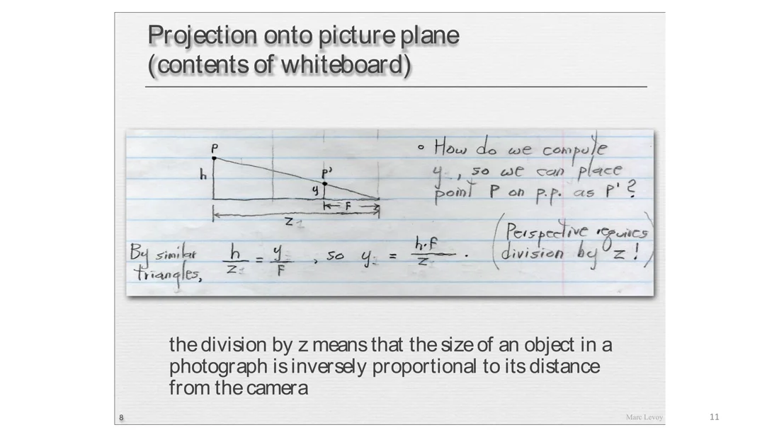
We want to project a point at height and depth onto the picture plane, i.e. find its image height . The picture plane is at distance from the viewpoint (the focal length). By similar triangles:
Perspective projection
Intuition
The mapping requires a division by , so it is a non-linear projection. The size of an object in a photograph is inversely proportional to its distance from the camera: if I am twice as far away, I appear half as big.
Exam relevance
This formula is the one to know best (“pinhole camera, lecture 2 slide 11”). The calculation tasks in the exam used it in both directions. See Worked Examples.
Vanishing Points
Slides 12-18
In linear perspective, straight lines remain straight. But parallel lines don’t remain parallel: objects appear smaller the further away they are, so parallel lines converge to a vanishing point.
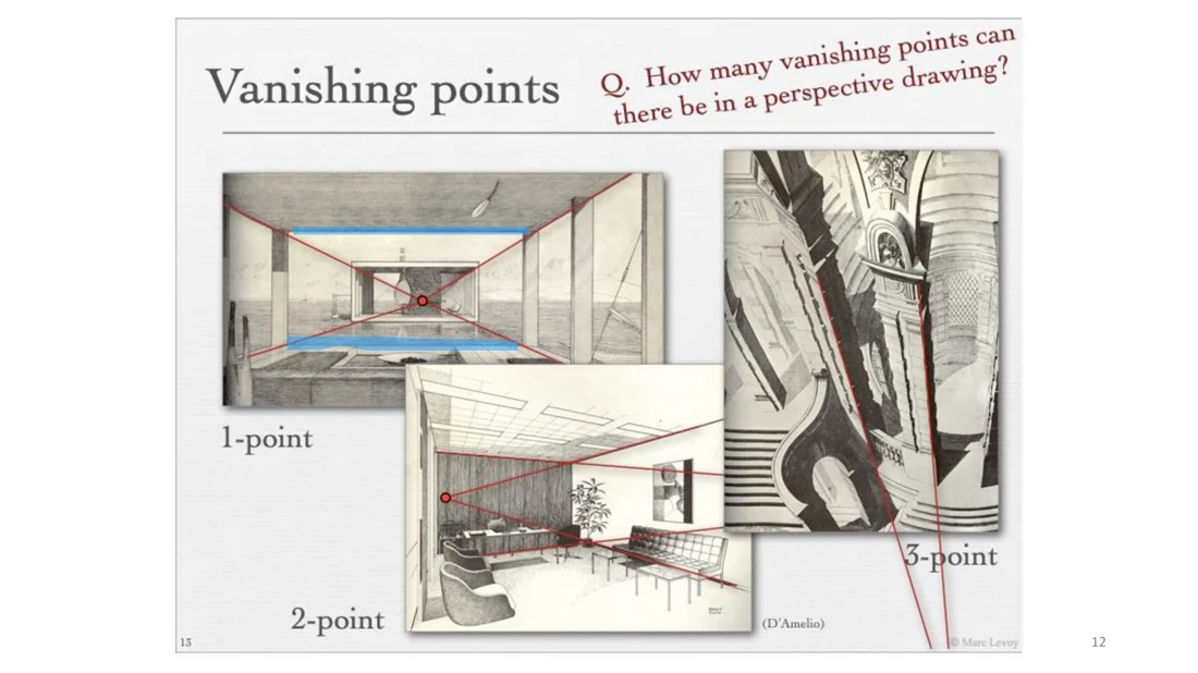
How many vanishing points can there be in a perspective drawing?
Answer Infinitely many. Every family of parallel lines in the scene converges to its own vanishing point. "1-point, 2-point, 3-point" only describes the main axes of a box.
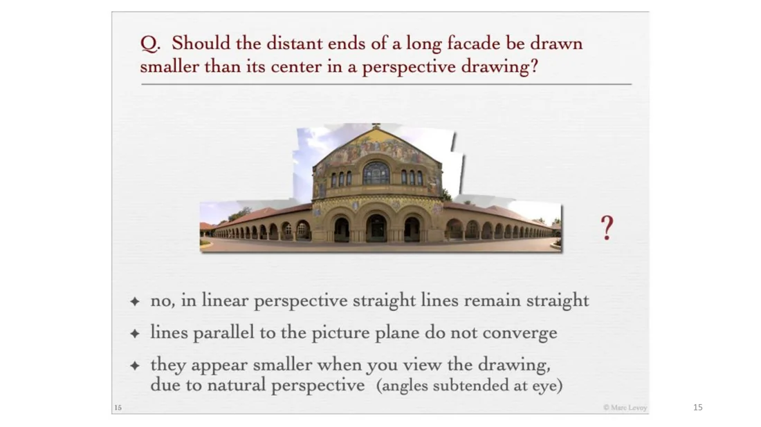
Should the distant ends of a long facade be drawn smaller than its center in a perspective drawing?
Answer No. In linear perspective straight lines remain straight, and lines parallel to the picture plane do not converge. The ends only appear smaller when you look at a very large drawing, because of natural perspective (the angles subtended at your eye).
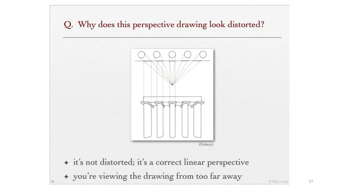
Why does this perspective drawing of columns look distorted?
Answer
It is not distorted, it is a correct linear perspective. We are viewing the drawing from too far away. To see it undistorted, we would have to stand really close to the picture (at its viewpoint).
Recap (Slide 18)
- Natural perspective: the visual angle subtended by a feature in the world.
- Linear perspective: intersections of lines of sight with a picture plane. The correct way to make a drawing on a flat surface.
- Vanishing points: one per direction of line in the scene. Lines parallel to the picture plane do not converge.
From Pinhole to Lens
Slides 19-27
A camera like the Nikon F4 (SLR) contains a lot of glass: the lenses. Do cameras need lenses? Can we just put a sensor?
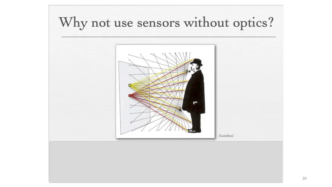
Why not use sensors without optics?
Slide 20
Every location on the sensor would receive the integral of rays coming from many different places in the scene. Nearby image locations would get almost the same color, and the whole image would be blurred.
Pinhole camera (camera obscura)
Slides 21-22
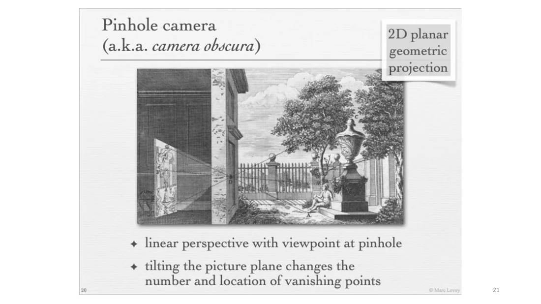
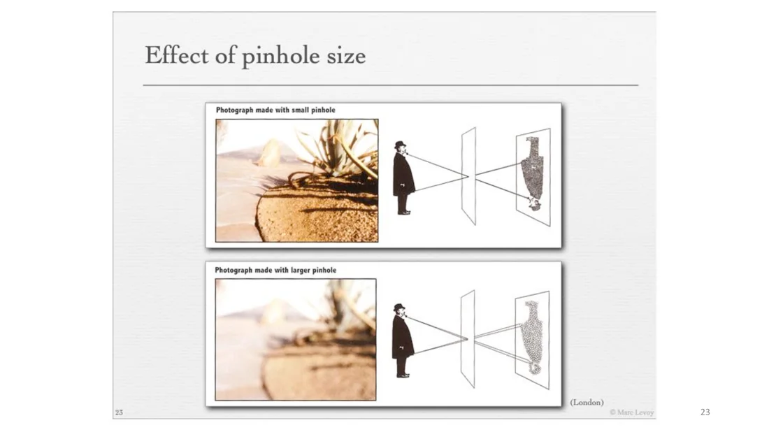
Since ages it is known that you can make a hole in a wall and put a sensor (or a white wall) on the other side. This pinhole camera or camera obscura gives an image with linear perspective, with the viewpoint at the pinhole. Everything is in focus. The image is inverted: a ray from the top of the scene lands at the bottom of the image and vice versa. Tilting the picture plane changes the number and location of the vanishing points.
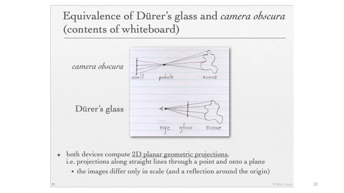
In the pinhole model, the image is produced behind the pinhole. A completely equivalent model puts the image plane in front of the pinhole (Dürer’s glass). Both compute 2D planar geometric projections (along straight lines through a point onto a plane). The images differ only in scale and a reflection around the origin. The front model makes the similar-triangle math easier, so we use it from now on.
Effect of pinhole size
Slides 23-24
Problem: a pinhole does not let enough light through. If we make it larger, all rays that arrive at one pixel form a cone. Every pixel becomes the integral over a region of the scene, so the image looks blurry, even for small pinholes. That is why real cameras don’t use pinholes.
Replacing the pinhole with a lens
Slides 25-27
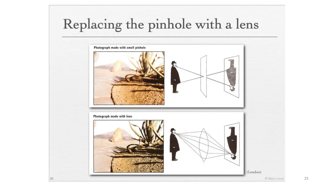
A lens takes all the rays leaving one point and brings them back to a single point. It still gives a linear perspective:
- A lens replaces the pinhole, and the film or digital sensor becomes the picture plane.
- The effective linear-perspective rays are the straight rays through the middle of the lens. So the effective pinhole is at the center of the lens.
- Rotating the camera (and lens) around the lens center adds or removes vanishing points.
Geometrical optics: two principles
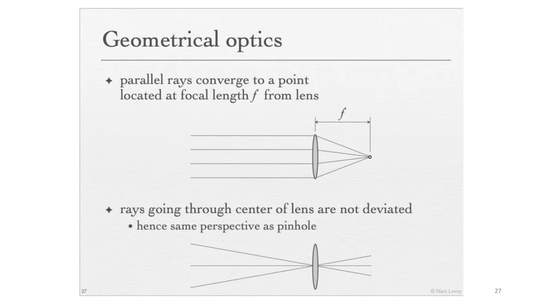
- Parallel rays converge to a point located at the focal length from the lens.
- Rays going through the center of the lens are not deviated, hence the same perspective as a pinhole.
Pretty much everything else can be derived from these two.
The Gaussian Lens Formula
Slides 28-35
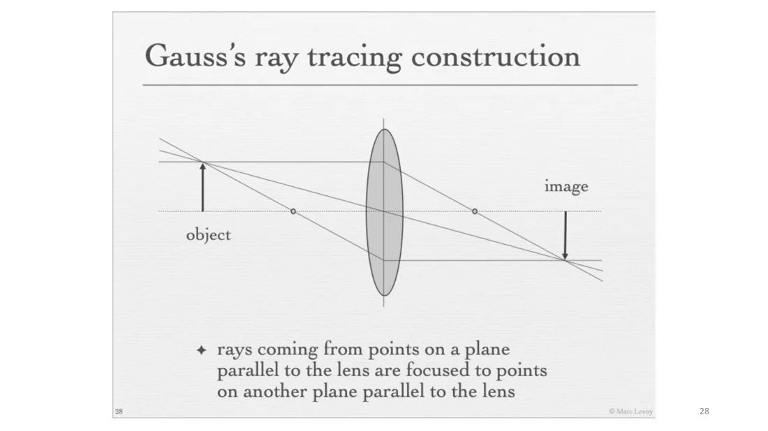
Gauss’s ray tracing construction
Slide 28
A consequence of the two principles: points on a plane parallel to the lens are focused to points on another plane parallel to the lens. Take the top ray from an object point: it is bent to pass through the focal point and hits the image plane at some height. The ray through the front focal point is bent to leave the lens parallel and hits exactly the same point.
Changing the focus distance
Slides 29, 33
The focal length is where parallel rays converge, and parallel rays come from objects at infinity. If we move the sensor relative to the focal point, rays from objects at a finite distance are focused into a single point. So objects at a fixed distance get in focus.
- To focus on objects at different distances, move the sensor relative to the lens.
- In a handheld camera, one actually moves the lens, not the sensor.
- By convention, the focus distance is on the object side of the lens.
Derivation
Slides 30-32
Conventions: positive is rightward, positive is leftward, positive is upward. is the object distance, the image (sensor) distance, the object height, the image height.
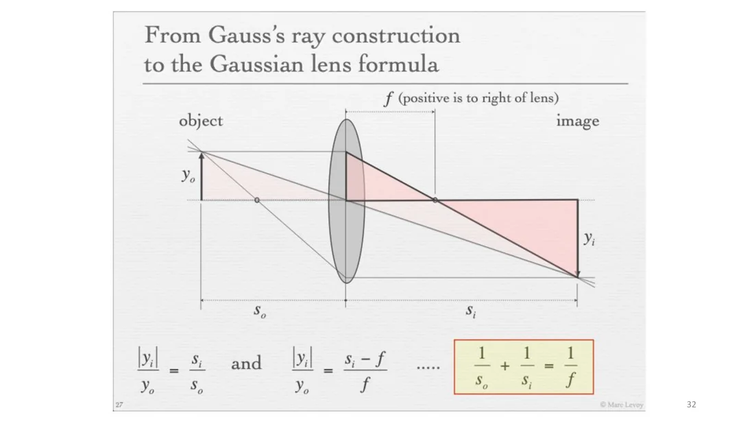
Derivation step by step
Triangles through the lens center (Slide 31):
Triangles through the focal point on the image side (Slide 32):
Setting both equal and dividing by :
Gaussian lens formula
For a lens with fixed focal length , it tells us how far the sensor has to be from the lens to focus an object at distance (or how much to change the focal length).
Pinhole camera model vs. lens camera model
Slides 34-35
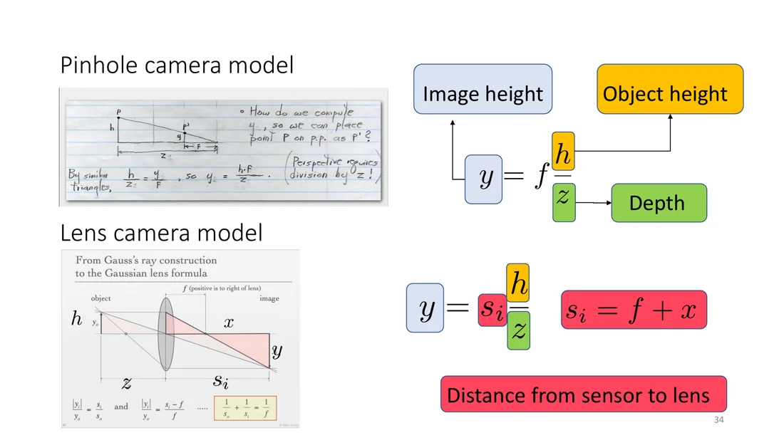
| Pinhole camera model | Lens camera model | |
|---|---|---|
| Image height | , with | |
| Meaning of | distance from the pinhole to the image plane | a physical property of the lens: the distance at which parallel rays converge. Does not depend on the sensor position |
| Linear perspective set by | , the distance from sensor to lens |
From the lens formula (with object depth ): as the depth goes to infinity, , we get .
Intuition
A lens with focal length is equivalent to a pinhole at distance . This is why in computer vision we typically work with the pinhole camera model and don’t think about lenses, unless we need to undistort images.
Two meanings of f
In the pinhole model, is the sensor distance. In the lens model, is a property of the lens and the perspective is set by .
Focal Length, Field of View and Viewpoint
Slides 36-42
Changing the focal length
Slide 36
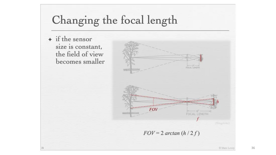
If the sensor size is constant, a larger focal length gives a smaller field of view. The field of view is two times the angle of the half triangle:
Field of view
Larger focal length → smaller field of view. That is why the field of view gets narrower when we zoom.
Changing the sensor size
Slide 37
- If the sensor is smaller, the field of view is smaller too.
- Smaller sensors either have fewer pixels, or smaller pixels, which are noisier.
Changing the focal length vs. changing the viewpoint
Slides 38-40
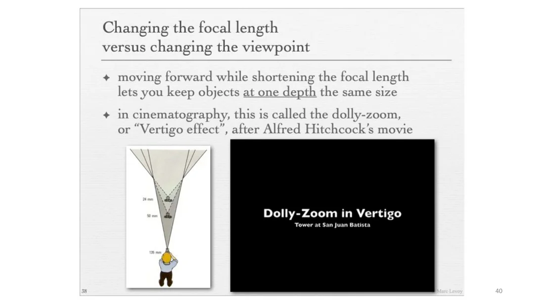
- Changing the focal length lets us move back from a subject while keeping its size in the image.
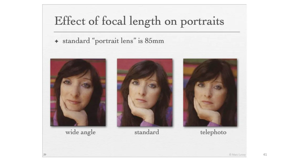
- But moving back changes the perspective relationships. In the photos below, the front subject has the same size in all three. With the telephoto lens (camera moved back), the subject in the back appears bigger relative to the front subject: the focal length is very large, so the difference in depth matters less for the difference in image size.
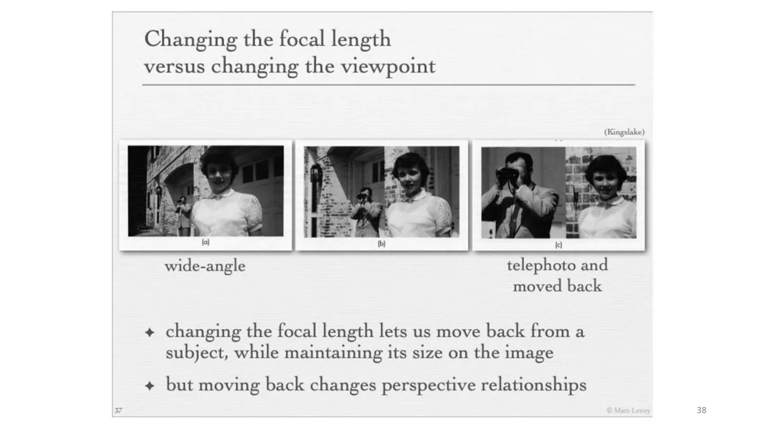
Moving forward while shortening the focal length keeps objects at one depth the same size. In cinematography this is the dolly-zoom or “Vertigo effect”, after Alfred Hitchcock’s movie.
Effect of focal length on portraits
Slide 41
The standard “portrait lens” is 85 mm. For faces this effect is very important. Remember the division by depth: close to the camera, depth differences matter a lot, so we get strong perspective effects (a big nose with a wide-angle lens). Far away, a small depth difference (nose vs. eyes) is negligible.
Recap (Slide 42)
- Pinhole cameras compute correct linear perspectives, but they are dark.
- Lenses gather more light, but only one plane of the scene is in focus. The distance from the lens to this plane is the focus distance. We change what is in focus by moving the sensor or the lens.
- The focal length determines the field of view (from wide angle to telephoto), and the field of view depends on the sensor size.
Part 2: Image Formation, Projection Matrix
The goal now is to express the image formation process using a single projection matrix.
Imaging Geometry: Four Coordinate Systems
Slides 43-51
- An object of interest is given in a world coordinate system , which can be different from the camera coordinate system.
- The camera coordinate system : by convention the axis is the optic axis of the camera. The image plane is located units out along the optic axis ( is the focal length). We use the equivalent model with the image plane in front of the camera center.
- Forward projection onto the image plane: the 3D point is projected to the 2D film coordinates . These are still metric units (e.g. centimeters).
- The image then gets digitized into pixel coordinates . Units are pixels.
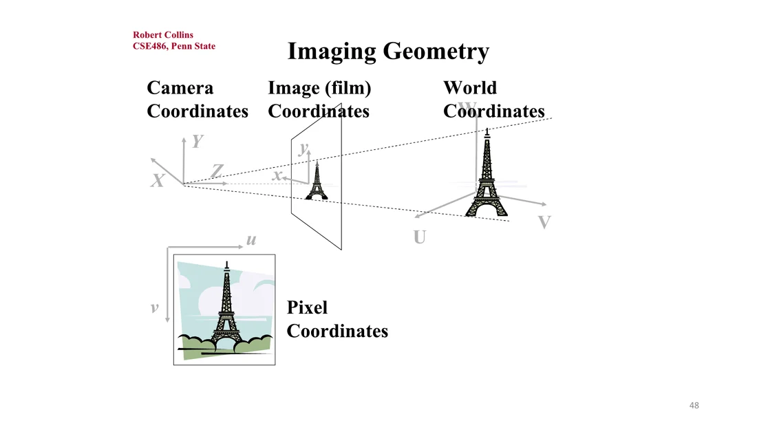
flowchart LR
  W["World coords<br/>(U, V, W)"] -- "rigid transformation<br/>M_ext" --> C["Camera coords<br/>(X, Y, Z)"]
  C -- "perspective projection<br/>M_proj" --> F["Film coords<br/>(x, y)"]
  F -- "affine transformation<br/>M_aff" --> P["Pixel coords<br/>(u, v)"]
So there are three transformations:
- World → camera: a rigid transformation (rotation + translation).
- Camera → film: the 3D-to-2D perspective projection.
- Film → pixel: depends on the sensor hardware (pixel size, principal point).
We want to describe this sequence by one matrix equation. A matrix means a linear mapping, which the projection is not. We will use a trick (homogeneous coordinates) to write it as a linear mapping anyway.
Forward vs. backward projection
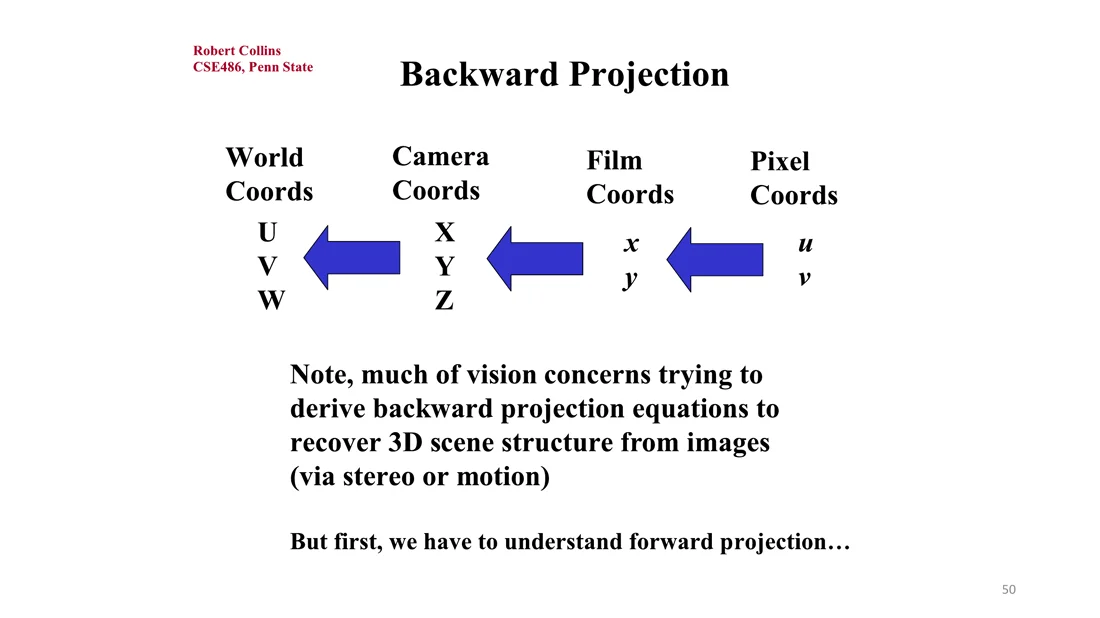
Much of computer vision is about backward projection: deriving equations that recover the 3D scene structure from images (via stereo or motion, by triangulation, or with learned priors). Structure from motion follows in Lecture 3. But first we have to understand the forward projection, which is the computer graphics problem.
Trap
Only camera → film loses information: the division by throws away the depth. World → camera and film → pixel are invertible.
Basic Perspective Projection
Slides 52-55
We start in the middle of the chain: camera coordinates to film coordinates. A scene point is projected to the image point by linear perspective. For the direction: is to as is to . The direction works exactly the same way.
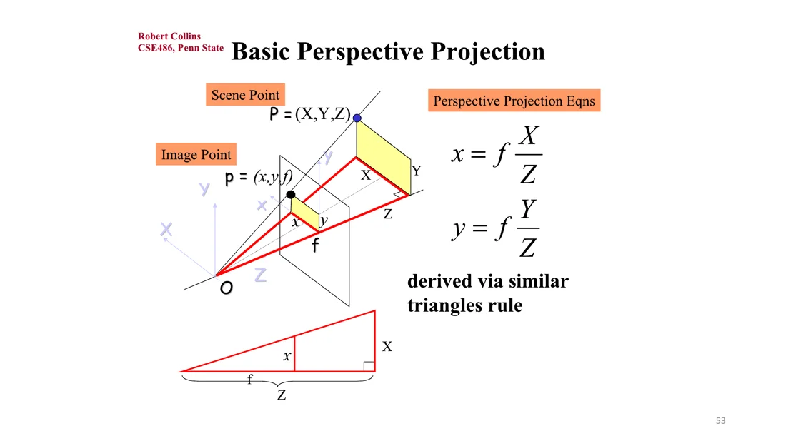
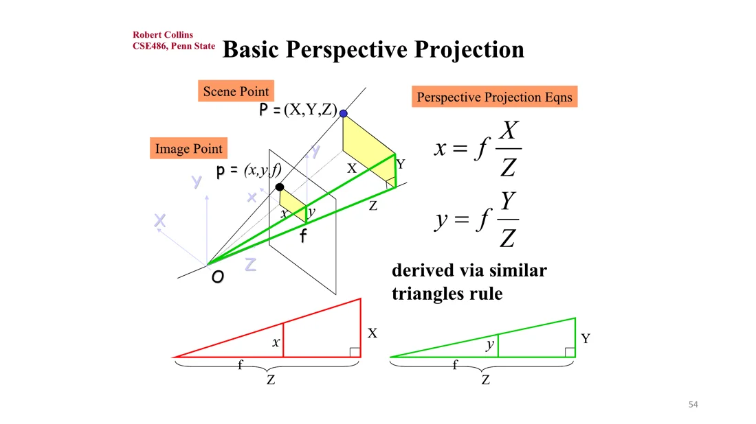
Perspective projection equations
How do we write this as a matrix equation? The division by makes the mapping non-linear, so we need homogeneous coordinates.
Why no matrix works in normal coordinates
Scale the 3D point by : . The image does not change. A linear map would scale the result by .
Homogeneous Coordinates
Slides 56-57
Homogeneous coordinates
Represent a 2D point by a 3D point by adding a “fictitious” third coordinate. By convention, the 2D point is recovered as
Scaling does not change the point:
( can be negative as well as positive.)
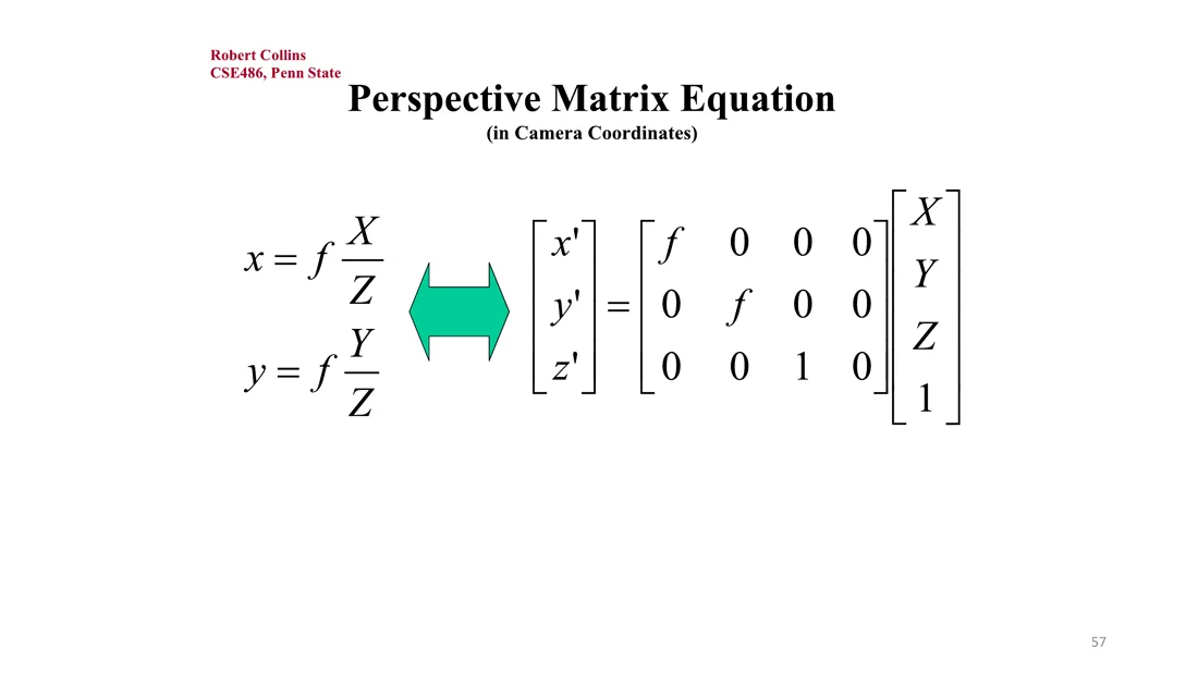
With this change of coordinates, the perspective projection becomes linear and can be written as a matrix:
Perspective matrix equation (in camera coordinates)
Dividing by gives back and .
Trap
The non-linearity is not gone, it is moved out of the matrix: the division happens at the end, when we go back from homogeneous to normal coordinates.
World to Camera: Extrinsic Parameters
Slides 58-71
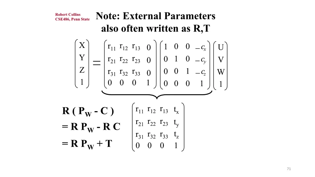
The first transformation, from world to camera coordinates, is a rigid transformation (rotation + translation) between the world and camera coordinate systems. It is a simple change of coordinates.
To express a point in camera coordinates:
- Translate by to align the origins ( is the camera center in world coordinates).
- Rotate by to align the axes.
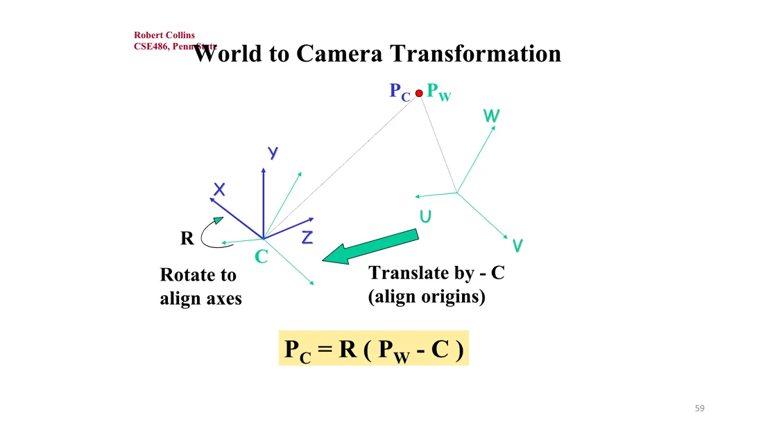
World to camera
In homogeneous coordinates:
Columns of R
The columns of are the axes of the source coordinate frame expressed in the target coordinate frame (more on rotations in Lecture 2.2). So is the world axis in camera coordinates. If camera and world frames are aligned, this column is : 1 times the axis plus 0 times the and axes.
Example: simple stereo system
Slides 61-64
The world axes are aligned with the left camera. The left camera is at the world origin , the right camera at , both with axes aligned with the world axes.
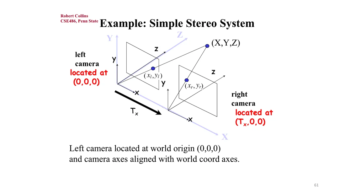
- Left camera: rotation and translation are both the identity, so the transformation is the identity.
- Right camera: the axes are aligned, so the rotation is the identity, but the origin is translated by (the camera center in world coordinates is ).
Simple stereo projection equations
This setup comes back in Lecture 4 (disparity ).
Figuring out rotations
Slides 65-69
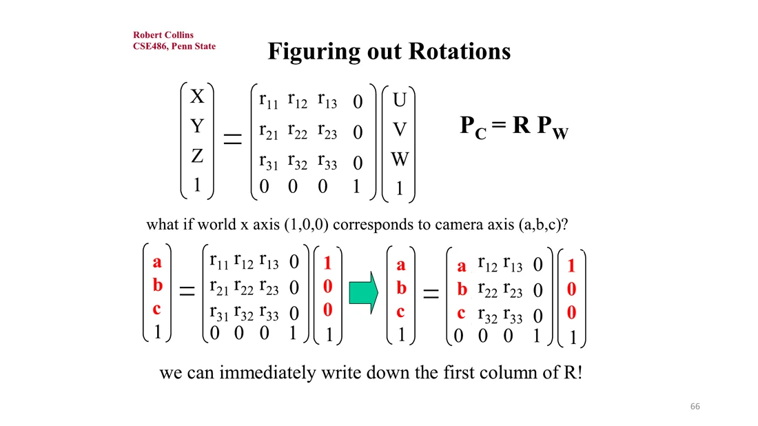
When thinking about rotations, forget about the translation: the rotation is a property of the axes alone. The equation says how vectors in the world coordinate system (including the coordinate axes) get transformed into the camera coordinate system.
Method 1: if we know that the world axis corresponds to the camera axis , then
and we can immediately write down the first column of . Likewise with the world and axes for the other columns.
Method 2: sometimes it is easier to specify what the camera , or axis is in world coordinates. Then rearrange (R is orthogonal):
Now the rows of are the camera axes in world coordinates.
External parameters as R, T
Slide 70
Extrinsic parameters
T is not the camera position
is the camera center in world coordinates. . Only if is .
Summary so far (Slide 71): we know how to transform 3D world points into camera coordinates, and then do a perspective projection to get 2D points in the film plane. Next: pixel coordinates.
Film to Pixel: Intrinsic Parameters
Slides 72-80
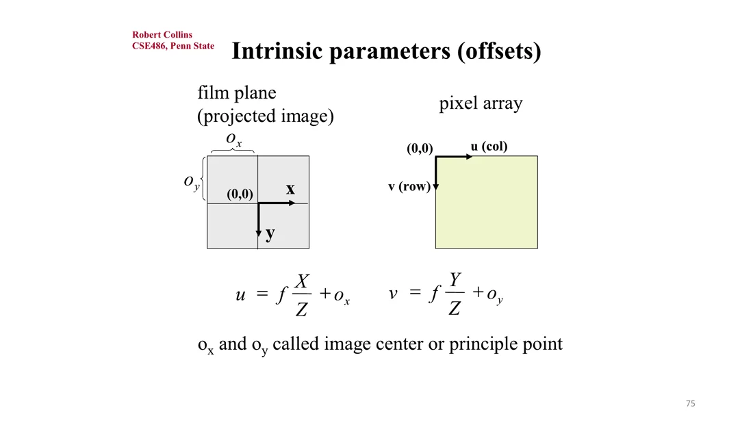
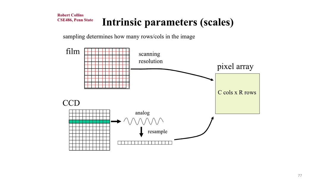
The film-to-pixel step is an affine transformation. The intrinsic parameters describe the coordinate transformation between film coordinates (the projected image) and the pixel array. They depend on the hardware of the sensor: how large the pixels are, what shape they have, and so on. For film cameras this is the scanning/digitization, for CCD cameras the grid of photosensors.
Offsets: the principal point
Slide 74
The film plane has its origin in the center. The pixel array has its origin in the top left corner ( = column, = row). In principle the center of the sensor is the principal point, so we translate by :
and are called the image center or principal point.
Flipped axes
Slide 75
Sometimes one or more axes are flipped, e.g. the film and correspond to and :
Tip
This is a common bug: if your own renderer shows a flipped or cropped image, it is usually a problem with the axes.
Scales
Slides 76-77
The sensor captures an analog signal that is resampled into a pixel array. This discretization step decides how many rows and columns the image has (the resolution). At the same scanning resolution, a bigger sensor gives a higher resolution. This gives a scale from film to pixel coordinates, possibly different in and :
Effective scales
are the pixel sizes. Since the scale factors can differ, pixels are not necessarily square. The aspect ratio is .
Perspective projection matrix
Slide 78
Adding the intrinsic parameters into the perspective projection matrix gives the intrinsic camera matrix. It depends on the hardware of the camera, not on where the camera is relative to the world.
Intrinsic matrix
To verify: and .
Note (Slide 79): sometimes image and camera coordinate systems have opposite orientations (the book does it this way). Then and the matrix gets and on the diagonal.
Note 2 (Slide 80): we can also think of the conversion as two separate transformations: a projection and a 2D affine transformation from film coordinates to pixel coordinates :
Summary: Forward Projection
Slide 81
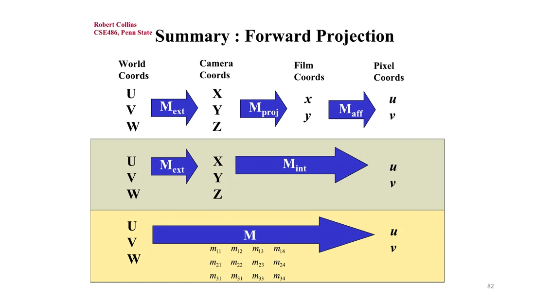
Full projection
The tilde means homogeneous coordinates. : where the camera is (, ). : how the camera is built (, , , , ).
This perspective camera model is the most commonly used camera projection model in computer vision and graphics.
Projection Models: Orthographic Projection
Slides 82-85
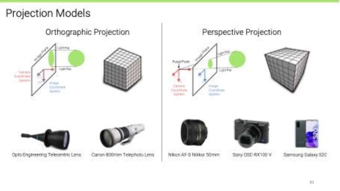
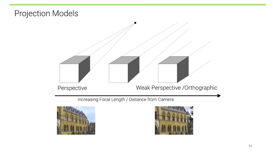
Sometimes an even simpler model is useful: orthographic projection, which completely ignores the linear perspective effects. It is a good model for telecentric lenses and telephoto cameras: the object is far away and the zoom is very large, so perspective effects can be ignored.
With increasing focal length and distance from the camera, the perspective effects disappear: perspective → weak perspective → orthographic.
Orthographic projection
Projection of a 3D point to pixel coordinates :
- The and axes of the camera and image coordinate systems are shared.
- Light rays are parallel to the axis of the camera coordinate system.
- During projection, the coordinate is dropped, and stay the same: .
Scaled orthographic projection
In practice, world coordinates (e.g. meters) must be scaled to fit onto the image sensor (pixels):
The unit of is px/m or px/mm.
Under orthography, structure and motion can be estimated simultaneously with factorization methods (e.g. via singular value decomposition). This is the Tomasi-Kanade factorization from Lecture 1.
| Perspective projection | Orthographic projection | |
|---|---|---|
| Equation | (scaled: ) | |
| Linear? | no, division by (needs homogeneous coordinates) | yes |
| Depth effects | far objects smaller, vanishing points | none |
| Good model for | normal cameras | telecentric and telephoto lenses |
Worked Examples
These are practice examples in the style of the calculation tasks from the exam. The numbers are made up.
Example 1: moving the camera back until two people look equally tall
Person A is m tall and stands m from the camera. Person B is m tall and stands m from the camera. The focal length is mm. How far does the camera have to move back (along the optic axis) until both appear equally tall?
Now: mm and mm. B looks taller.
Condition: equal image height means equal ratio ( cancels):
Check: . Both are mm tall in the image.
Example 2: focal length from object size, image size and depth
An object of height m at depth m appears mm tall on the sensor. What is the focal length?
Convert everything to the same unit first.
Example 3: from camera coordinates to pixels and back
Camera: mm, square pixels mm, principal point . So px. Point in camera coordinates: m.
Backward, if the depth is known:
Without , the pixel only gives a ray: every point with , lands on the same pixel. See Depth Ambiguity.
Exam relevance
- Calculation task from lectures 1-2: in both directions. Scenario from the exam: two people of different height, camera with a given focal length at a given distance: how far must the camera move back so both appear equally tall? Second part: compute from , and .
- A third calculation part probably involved the principal point and depth (not fully remembered).
- The four coordinate systems and which step loses information.
- Why homogeneous coordinates are needed.
- with .
- The intrinsic matrix and what each parameter means.
- Perspective vs. orthographic projection.
Self-Test
What is the difference between natural and linear perspective?
Answer subtended at the eye. Linear perspective (Brunelleschi) measures the height where the line of sight intersects the picture plane. The ratios differ: .
Natural perspective (Euclid) measures the visual angle
Derive the perspective projection equation and state its consequence.
Answer , so . Image size is inversely proportional to depth: twice as far, half as big.
Similar triangles:
Why is perspective projection not linear?
Answer gives : the image does not change. A linear map would scale the result by .
Scaling the 3D point by
Why don't we use a pinhole camera in practice, and what does a lens change?
Answer
A small pinhole is too dark. A larger one makes every pixel integrate a cone of rays, so the image is blurry. A lens gathers more light and brings all rays from one point to one point, with the same linear perspective (effective pinhole at the lens center). The cost: only one plane is in focus.
State the Gaussian lens formula. What does it give as ?
Answer . For , : a lens with focal length is equivalent to a pinhole at distance .
How does the field of view depend on the focal length?
Answer with sensor size . Larger , narrower field of view.
Name the four coordinate systems and the transformation between each pair. Which one is not invertible?
Answer → rigid transformation → camera → perspective projection → film → affine transformation → pixel . Camera → film is not invertible because depth is lost.
World
What are homogeneous coordinates and why do we need them here?
Answer for . They let us write the perspective projection as a matrix product; the division by moves to the end (dividing by ).
A point with an extra fictitious coordinate, defined only up to scale:
What do the columns of mean in ?
Answer has the camera axes in world coordinates.
They are the world axes expressed in camera coordinates (axes of the source frame in the target frame).
Is the camera position?
Answer with . is the camera position in world coordinates.
No.
Write down the intrinsic matrix and explain its parameters.
Answer . : focal length. : pixel sizes (aspect ratio , pixels need not be square). : principal point (moves the origin from the image center to the corner).
When is orthographic projection a good model, and how does it differ from perspective projection?
Answer (), so it is linear and has no perspective effects. Perspective projection divides by .
For telecentric and telephoto lenses (far away, large zoom). It drops
Related
- Previous: Lecture 1: Introduction · Next: Lecture 2.2: Rotations · Course: Overview
- Concepts: Pinhole Camera Model, Homogeneous Coordinates, Extrinsic Parameters, Intrinsic Parameters, Projection Matrix, Orthographic Projection, Vanishing Point, Focal Length, Depth Ambiguity